Polistan.ru
equipment for welding of polymers +7 919 999 44 55, +7 (495) 748-89-01,+7 (495) 748-89-02, +7 (925) 471 32 51
info@polistan.ru, office@polistan.ru
Moscow, Electrodnaya street, 8с2
Equipment
- Two-post HDTV machines
- Machines-Sliders HDTV
- Single-post HDTV machines
- Specialized
- Ultrasonic clock machines
- Ultrasonic sewing machines
HDTV machines for Stretch ceilings
Spare parts and consumables
- The electrode strips
- Equipment for HDTV welding
- Rollers
- Other spare parts
- Generator lamps
- Snap-in ultrasound

Главная » Directory and technologies
Directory and technologies
Table of polymer weldability by ultrasound
List of abbreviations for the most common polymers
ABS, ABS PLASTIC-acrylonitrile - butadiene-styrene
ASA-acrylonitrile-styrene-acrylate
BOPP, BOPP - biaxially oriented (biaxially oriented) polypropylene
C-cellulose polymers
COC-cycloolefin copolymer
CPP-cast polypropylene
IMOD modifiers
HDPE, HDPE, HDPE-high-density, low-pressure polyethylene
LDPE, LDPE, HDPE-low-density, high-pressure polyethylene
LCP-liquid transparent polymer
MABS-methyl methacrylate-acrylonitrile - butadiene-styrene
MF-melamine-formaldehyde
MPF-melamine-phenol-formaldehyde
OPP, OPP - oriented polypropylene
PA-polyamide
PBT-poly butylene terephthalate
PC-polycarbonate
PE, PE - polyethylene
PEI - polyetherimide
PEN-polyethylene-naphthalate
PES-polyester-sulfone
PET, PET, PET-POLY-ethylene terephthalate
PETG-polyethylene terephthalate, glycol
PF-phenol-formaldehyde
PI-polyimide
PK-polyketone
PMMA-polymethyl-methacrylate
POM-polyoxymethylene, polyformaldehyde
PP, PP - polypropylene
PPE - polyphenylene live
PPS-polyphenylenesulfide
PPSU - polyphenylsulfone
PS, PS-polystyrene
PS-SY-syndiotactic polystyrene
PSU-polysulfone
PTFE-polytetrafluoroethylene
PUR-polyurethane
PVC, PVC-polyvinyl chloride, "vinyl"
PVDF-polyvinylidene fluoride
SAN-styrene acrylonitrile
SB-styrene butadiene
SMAH-styrene maleic anhydride
RIGID FILM
PVC
PS (polystyrene) (KINDS OPS, UPS, BOPS)
PET (polyethylene terephthalate or dacron film)
BOPP (biaxially oriented polypropylene film)
OPS
PP
PE
ABS
POLYCARBONATE
DDCS
PVC/PE, PET, PET/PE
POLYESTER (70 -25250 D)
NYLON (70-2520 D)
LOW-ELASTIC POLYSTYRENE (ranging from 150 to 1800 d)
These types of rigid polymer films lend themselves well to thermoforming, have a wide range of colors, and allow you to implement even the most complex design solutions in the field of packaging.
But it is worth noting that the use of certain polymer films (in particular, pvc, polystyrene) for the manufacture of food packaging is limited by the requirements of the legislation of a number of european countries.
For example, in germany and a number of other european countries, the use of pvc for packaging is prohibited, because it is impossible to dispose of it without causing harm to the environment. pvc film is harmless to food, but when it is burned, chlorine is released. Refusing to burn does not solve the problem either, since it decomposes with the release of poison into the soil.
There are restrictions on the use of polystyrene for food packaging. when storing, even for a short time, products in polystyrene packaging (in particular, chocolates in boxes), the process of styrene emission begins. chocolate simply absorbs styrene, which is harmful to human health.
Pet is the most expensive raw material for the production of food packaging. But this is a higher molecular weight film (20 000 - 40 000), which eliminates the emission of any harmful substances from the material. The very base of the polymer obtained by polycondensation of terephthalic acid or its dimethyl ether with ethylene glycol does not harm the environment during decomposition.
ULTRASOUND WELDING METHODS
TABLE OF POLYMER WELDABILITY BY ULTRASOUND
HDTV WELDING TECHNOLOGY
Welding of plastics in an electric field - welding with a high frequency current (HDV), is performed by heating the material as a result of its absorption of electric field energy. HDPE welding, as well as ultrasonic welding (see below), provides fast and local heating of the connected surfaces without melting the entire volume of material and can therefore be used to connect materials with a narrow temperature range of the viscous state, with a high degree of orientation and high viscosity of the melt .
When welding HDPE, the material is located between metal electrodes, which forms a capacitor when this system is connected to a source of high-frequency electricity. Under the action of an electric field, the dielectric material is polarized. In the case of an alternating electric field, a variable polarization is formed in the dielectric, accompanied by a displacement of charged particles entering the atoms and molecules. The majority of real dielectrics (including thermoplastics), placed in an alternating field, has a certain conductivity.
A prerequisite for heating a polymer in a high-frequency electric field is the presence of links in its molecules that have a dipole structure and can be polarized when an external field is applied. When applying a polymer to an alternating electric field, microdipoles will be oriented in the direction of the electric field, that is, positive charges will be drawn to the negatively charged plate of the capacitor, and negatively charged ones-to the positive plate. When the charge sign changes on the capacitor plates, the orientation of the molecule sections will change. Neighboring links of the same molecule and neighboring molecules will prevent the change of orientation. The energy spent on overcoming these obstacles will be converted into heat. When heated, the polymer's viscosity decreases and the orientation conditions improve.
At a low frequency of change in the electric field, the dipoles of the dielectric are oriented without delay, and with increasing frequency of the field, the speed of rotation of the dipoles increases, and the friction of particles increases. At a very high frequency, the particles do not have time to make a full orientation and the polarization weakens.
Research shows that the process of heat generation in a high-frequency electric field is characterized by the parameters of this field (frequency and intensity), as well as the dielectric properties of the polymer. The heating rate does not depend on the thermal conductivity of the material, which only determines the heat loss in the near-ear zone and in the mass of the electrodes. In this regard, the maximum welding temperature is usually focused on the contact of parts, and the minimum - on the border of the product and the electrodes. This temperature distribution is an advantage of HDPE welding, since there is no external overheating of the material. Changing the intensity and frequency of the electric field increases the heating rate, but the increase in intensity is possible only up to a certain limit, above which there is an electric breakdown of the welded package located between the electrodes. This results in a marriage in the seam and violates the mode of operation of the RF generator.
The frequency of the electric field is also limited by the size of the capacitor. If certain ratios are violated, uneven heating of plastics may occur.
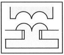
Methods of welding with high-frequency currents. Technologically, there are three methods of welding HDPE plastics: press, seam and spot. The choice of a particular welding method depends largely on the design features of products.
In the press method (Fig. 1, a), the welded parts are placed between the plates of the working capacitor - electrodes, one of which, or perhaps both, repeat the configuration of the seam. These electrodes are replaceable, that is, you can assign any form of seam.
Fig. 1 Diagrams of plastic welding in a high-frequency electric field:
1-electrodes, 2-weldable parts, 3-generator, 4-disks
When the voltage from the generator is applied to the electrodes, the necessary pressure is simultaneously applied to the parts to be welded. At the same time, the welding area along the entire length is heated simultaneously and evenly, which ensures high quality and stability of the mechanical properties of the weld. But this method of welding can connect parts with a thickness of no more than 5 mm.
Press welding is the most universal and common method. It is used not only for welding parts, but also for branding products, decorative finishing and applying applications.
Seam welding of HDPE (Fig. 1, b) is carried out by two disks rotating in opposite directions, which simultaneously with heating create pressure on the welded parts. Although seemingly simple, this method of welding has one serious drawback: to ensure high performance and a small welding area, it requires increasing the voltage and frequency of the current, that is, the specific power, which, as shown above, are limited. Therefore, the performance of this method is relatively low. In practice, this welding method is used relatively rarely and only for welding thin films.
Spot welding of HDPE (Fig. 1, b) is a type of seam, which differs from it in that the seam is not continuous in length, but discontinuous (individual points). This type of welding is used mainly for tacking products assembled for press or seam welding.
In a high-frequency field, you can weld cross-sections of pipes. However, achieving uniform heating along the entire perimeter of the joint is associated with certain difficulties. For welding pipes, use ring-shaped detachable or non-removable electrodes.
An important welding parameter here is the distance from the joint to the electrode, with a decrease in which the field strength in the joint increases, and therefore it is necessary to choose the optimal one.
Main technological parameters of HDV welding:
- electric field strength;
- the pressure value:
- the duration of heating.
Most polymer materials are effectively heated at a frequency of 10 ... 150 MHz. In order to ensure stability of operation and the absence of breakdowns, it is advisable to use the upper frequency limit, although the lower limit provides the maximum efficiency of the generator. The frequency of the electric field is normalized and determined by the frequency bands allowed for technical use. In order to avoid interference with radio broadcasting, television and other services in the Russian Federation, the frequencies allowed for HDTV welding are 27, 12; 40, 62; 81, 36; 152 MHz.
It should be noted that, unfortunately, such widely used thermoplastics as polyethylene, polystyrene, fluoroplast-4 and some others can not be connected directly by welding HDPE, since they are the most advanced dielectrics and can not generate enough heat for welding.
WELDING TECHNOLOGY ULTRASOUND
Powerful ultrasonic vibrations are widely used in industry, as well as in science for the study of certain physical phenomena and properties of substances. In engineering, ultrasound is used for metal processing and in flaw detection. It is widely used in medicine. In welding technology, ultrasound can be used for various purposes. By applying it to the weld pool during the crystallization process, the mechanical properties of the weld can be improved by grinding the structure of the weld metal and removing gases. Ultrasound reduces or removes its own stresses and deformations that occur during welding. One of the most promising applications of ultrasound is ultrasonic welding (UZS), which has received great development in recent years, both in our country and abroad.
The main distinctive features of UCS plastics are:
- possibility of welding on surfaces contaminated with various products;
- local heat release in the welding zone, which eliminates overheating of the plastic, as is the case when welding with a heated tool, heated gases, etc.;
- possibility of obtaining an all-in-one joint when welding rigid plastics at a great distance from the point of ULTRASONIC energy input;
- ability to perform connections in hard-to-reach places;
- with ultrasonic heating, the material is heated to the welding temperature quickly; the heating time is calculated in seconds and fractions of a second.
The developed equipment is supplied for the following technological operations:
- ultrasonic welding of plastics (polystyrene, ABS plastic, polyethylene, Dacron, nylon, etc.) used in food, chemical, aviation, automotive and other industries;
- ultrasonic cutting of thermoplastic materials-polymers of various brands, paper, films, etc.;
- reinforcement of plastics with metals, rolling rivets made of polymer, threading in plastic, joining plastics with metals;
- production of non-woven materials based on polypropylene, nylon, Dacron, etc., with their subsequent connection to each other by ultrasound;
- ultrasonic stamping on polymers and leather.
The method of ultrasonic testing of plastics consists in the fact that the electrical vibrations of the ULTRASONIC frequency (18-50 KHz) generated by the generator are converted into mechanical vibrations of the welding tool - waveguide and introduced into the material being welded. Here, part of the energy of mechanical vibrations passes into heat, which leads to heating of the contact zone of the connected parts to the temperature of the viscous state. To ensure proper conditions for entering mechanical vibrations and creating a close contact of the welded surfaces, pressure is applied between the waveguide and the support. This contact is provided by the static pressure of the PCT. working end of the waveguide on the welded parts. This pressure also contributes to the concentration of energy in the junction zone. The dynamic force F, resulting from the oscillating waveguide, leads to the load of the material being welded, and the action of static pressure PCT. provides a strong welded joint. Mechanical vibrations and pressure in this case act in a line perpendicular to the welded surfaces. This energy input scheme is used for UCS plastics in contrast to the " metal scheme, when mechanical vibrations act in the plane of the connected surfaces, and the pressure is perpendicular to them. The power supply from the waveguide can be one-way or two-way.
According to the nature of energy transfer and its distribution on the welded surfaces, the ultrasonic system is divided into contact and transfer.
The ability to transfer mechanical energy to the welding zone depends on the elastic properties and the damping coefficient of vibrations and the materials being welded. If the polymer is characterized by a low elastic modulus and a large attenuation coefficient, then the weld can be obtained only at a small distance from the vibration input plane. Welding according to this scheme is called contact ultrasonic welding. Contact UZS is usually used for connecting products made of soft plastics, such as polyethylene polypropylene PVC, as well as films and synthetic fabrics of small thickness - from 0.02 mm to 5 mm. In this method of welding, lap joints are most common.
If the polymer has a high modulus of elasticity and a low attenuation coefficient, the weld can be obtained at a great distance from the input of mechanical vibrations. welding according to this scheme is called transfer UZS. Transfer welding is recommended for joining bulk parts made of rigid plastics, such as polystyrene, polymethylmethacrylate, nylon, etc. Here the connections get butt-to-butt, vtavr. Removal of the input surface of mechanical vibrations from the interface plane of the welded parts depends on the elastic properties of the material and can range from 10 to 250 mm.
It is established that the development and formation of a welded joint depends on the degree of stress concentration in the welding zone and can be intensified by creating artificial stress concentrators. The most common method of welding using artificial concentrators is edge-cutting welding, and the best results are obtained when one of the parts has a V-shaped protrusion. Stress concentration can also be created when the surface roughness increases, or when crumbs of the same material are poured on the surfaces to be welded.
Depending on the movement of the waveguide relative to the product, the ultrasonic system is divided into a press and a continuous one.
Press welding is performed in one movement of the waveguide and is used for both contact and transfer welding.
Continuous welding provides continuous extended welds due to the relative movement of the waveguide and the products being welded and is used for welding products made of polymer films from synthetic fabrics, bags, filters, etc.both manual and mechanized welding is used here. For continuous welding, fixed draft and fixed gap schemes are used.
The possibility of obtaining welded joints is determined by the amount of heat energy released in the connection zone and the heat sink from this zone. Since the amount of energy released in the welding zone is determined by the amount of energy introduced into the product being welded, it becomes necessary to dose the latter.
According to the principle of dosing the input mechanical energy ultrasonic welding is divided into welding:
- with a fixed flow time of the ultrasonic pulse;
- fixed draft;
- with a fixed gap;
- with energy metering according to the kinetic characteristic (by changing the amplitude of the displacement of the support).
The main parameters of ultrasonic welding, which characterizes the energy release in the connection area, and the vibration amplitude of end face of waveguide A (microns; the oscillation frequency f (kHz); the duration of the ultrasonic pulse t DM/s/ or in the case of continuous welding, the welding speed V St /m/s/ welding static pressure PCT. /PA/ or enhancement pressing F /n/ of the waveguide to the material.
Additional parameters of the welding mode - dimensions, shape and material of the support and waveguide, material of thermal insulation gaskets; preheating temperature of the waveguide, etc. The main parameters of the mode are interrelated. The time required for welding depends on the oscillation amplitude and welding pressure. At higher amplitudes, the required properties of welded joints can be achieved with less welding time, and Vice versa. The determining parameter of the ultrasonic welding mode is the oscillation amplitude of the working end of the waveguide, which is selected within the range of 30-70 microns. The optimal value of the amplitude corresponds to the maximum strength and best quality of the welded joint. The oscillation amplitude required to ensure high-quality welding is related to the welding pressure and, in addition, depends on the geometric dimensions of the parts to be welded, the type of polymers to be welded, and the support that determines the distribution of the sound field characteristics.
The optimal parameters of the welding mode depend on the properties of the material being welded, the thickness and shape of the products and other factors and are set in each case experimentally to real products. The mode is usually evaluated based on the strength of the welded joint. In addition, it is checked for tightness, deformation and other characteristics.
The properties of welded joints depend not only on the parameters of the welding mode, but also on the working cycle. The operating cycle is determined by the sequence of applying pressure, enabling, passing and disabling the ultrasonic pulse, holding the product under pressure and removing pressure. The welding cycle is the basis for selecting the pressure mechanism scheme and enabling ultrasonic vibrations of welding machines.
The most common working cycle of ultrasonic welding is statistical pressure-ultrasound. Statistical pressure PCT. is applied before the inclusion of ultrasonic vibrations, remains constant throughout the cycle and is removed with a delay, after the formation of the welded joint. Cooling of the weld material begins when the parts are still compressed between the waveguide and the support. During the entire welding operation, ultrasonic vibrations are introduced without interruption in the form of a single pulse.
In the ultrasound - statistical pressure cycle, ultrasonic vibrations are activated until the pressure is applied. The initial activation of ultrasound allows you to clean the welded surfaces from contamination.
Production of non-woven materials.
A new method of manufacturing non-woven materials has been developed, according to which the canvas fibers, oriented or distributed randomly, are bonded by ultrasonic welding. In this case, the canvas may consist of thermoplastic fibers (polypropylene, nylon, Dacron, chlorine, etc.) or from smechi them with cotton, viscose, wool and other non-thermoplastic fibers. In the latter case, the softened thermoplastic component envelops the non-thermoplastical fibers, thereby forming strong connections. Since fiber canvases are characterized by a large attenuation coefficient, their bonding can be performed according to the scheme of contact ultrasonic welding. For continuous implementation of the process, the most acceptable method of seam welding with step-by-step movement of the material, since in this case, deformations and breaks of the loose canvas are prevented both during the welding process and during the transportation of the finished material to a given step. In this case, the welds can be laid both in the direction perpendicular to the longitudinal axis of the canvas, and at an angle to the axis. Extended seams can be obtained by using multiple waveguides installed in such a way that the necessary overlap of the welds is provided.
Welding of artificial leather.
Artificial leather (IR) is obtained by applying a polymer material to a woven base made of natural or synthetic fibers.
Of the entire range of manufactured, currently produced IRS, 70% are leather with polyvinyl chloride (PVC) coating. PVC coating is a multi-component system that includes additives of stabilizers, plasticizers, fillers, modifiers and other components, the introduction of which allows you to significantly change the properties of the polymer. Thus, depending on the type and quantity of plasticizers, the flow temperature of the PVC coating is in the range from 370 to 440 K.
Ultrasonic welding can successfully weld IR through non-thermoplasticized sheet or film substrates made of a material that is combined with the IR coating material, as well as in the presence of an intermediate layer, such as polyurethane foam (PUF), between the layers of IR or IR and the substrate. When manufacturing interior trim elements for vehicle interiors, it is necessary to connect IR and PVC substrate through an intermediate layer of PU.
The strength of IR welded joints and the stability of mechanical properties are greatly influenced by the welding process control scheme. the best results are achieved when welding with a limit of the seam thickness within 0.7-0.9 of the total thickness of coatings or coatings and PVC substrates. When testing welded joints for delamination, destruction occurs by peeling the coating from the base.
Welding of hard plastics.
Welding of polystyrene, styrene copolymers, polymethylmethacrylate, caprolon, polycarbonate and other polymers with a high elastic modulus and low attenuation coefficient is widely used in the manufacture of various bulk parts and structures: from containers and vessels to consumer goods (sports products and toys). In this case, ultrasonic welding can significantly reduce the labor intensity of the process, increase labor productivity, improve production culture and get rid of the use of toxic adhesives that are harmful to human health.
Depending on the shape of the product and material, contact and transfer welding or a combination of these methods can be used. During transfer welding, there is no need to heat up the entire volume of material. The weld is obtained by melting the polymer in the contact zone of the parts. It is clear that during the welding process, one should strive to concentrate the energy of ultrasonic vibrations directly on the joined surfaces. By changing the geometry of the parts to be welded, you can concentrate the energy of ultrasonic vibrations in one or another combination, which allows you to speed up the welding process.
We recommend a variety of shapes and sizes of joints of parts for ultrasonic welding, depending on specific products and materials, but the most common is the V - shaped cutting of edges, which is easy to manufacture and gives good indicators of the strength of welded joints. The most effective angle at the top of the V - shaped protrusion is 90°, which provides a minimum contact area of the parts before welding.
Small-sized parts of simple shape are welded in one contact of the waveguide with the product, and the waveguide is installed perpendicular to the welded surfaces, along the axis of symmetry. if the part is complex and the length of the weld is significant, the number of points and the place of introduction of ultrasonic vibrations is determined experimentally. Depending on the shape of the injection product, waveguides with a flat or curved working surface can be used for welding. In the latter case, the working end of the waveguide is adjacent to the surface of the welded parts, copying its shape. This is necessary when you need to get a sealed seam.
Various holding devices can be used for fixing parts: nest-shaped, spherical supports, etc. Optimal welding mode: time 3 s; amplitude 40-40 microns; compression force 50-150 N; frequency 22 kHz.
Cutting with simultaneous welding of plastics.
Recently, methods of ultrasonic cutting with simultaneous welding of plastics and biological tissues have been widely used in industry and medicine. In this case, the productivity increases up to 10 times compared to mechanical cutting methods.
The essence of the method is that elastic mechanical vibrations of ultrasonic frequency are applied to the waveguide tool, whose geometry is determined by the density of the material being cut. This allows you to significantly reduce the cutting force, improves the quality of the treated surface in the absence of destruction of polymers such as polystyrene, plexiglass, polypropylene, polyethylene, polyamide, etc.
The waveguide tools used are exponential rods with a cutting part in the form of a knife with a special sharpening, made of titanium alloys, as well as 45 and 30 hgsa steel.
When cutting plastics, you can move either the waveguide itself-the knife, or the part. The waveguide knife in the process of cutting pushes the cut material up using a longitudinal bevel (cutting edge), and the other side makes the alignment of the surface of the part. In this case, there is no waste in the form of chips and sawdust and a good quality of the cut is obtained. The cutting part of waveguide tools can be of various geometric shapes depending on the required geometric parameters of the product: round, square, rectangular, plate, disk, etc.
Welding and cutting methods can be used in combination. This has a significant effect, for example, if you need to weld two parts at the ends and simultaneously separate them along the weld from each other. This method allows you to seal various products in plastic tubes.
Main elements of UCS machines:
welding unit (acoustic unit), support, pressure mechanism, mechanism for moving moving elements, mechanism for switching on and off of the ultrasonic device, auxiliary device and frame (housing).
Machines for the Assembly of plastics are divided into machines for contour point press welding, seam and seam-step welding. Used portable installation, for example, hand guns, low power. The machine power from 100 W to 1.5 kW. The most common frequency welding machines is 20-22 KGV.
The most important node that forms the basis and includes the specifics of equipment and technology for ultrasonic welding of plastics is the Electromechanical oscillating system (welding unit). An Electromechanical oscillating (acoustic) system is used to convert electrical vibrations of an ultrasonic frequency generated by an ultrasonic generator into mechanical vibrations of the same frequency. Ultrasonic vibrations are those whose frequency exceeds 16,000 Hz (4.5). In addition, the acoustic system performs the functions of transmitting this energy to the welding zone, matching the load resistance with the internal resistance of the system, and the geometric dimensions of the energy input zone with the dimensions of the Converter-emitter. The welding unit provides the necessary oscillatory speed at the working end of the waveguide at the maximum efficiency at the resonant frequency, regardless of the load change, and is 30-60 microns. Ultrasonic vibrations are elastic waves that propagate in any material medium that is in a solid, liquid or gaseous state. The appearance of elastic waves is due to the fact that when a certain point of the elastic medium is displaced by an external force, forces arise that tend to return the point to the equilibrium position.
The conversion of electrical energy into the energy of mechanical elastic vibrations is based on the use of a magnetostrictive or piezoceramic effect. Without dwelling on the physical nature of these phenomena, which are covered in detail in the special literature, we will only point out that they are characteristic of ferromagnetic (in the case of magnetostriction) and piezoceramic (in the case of electrostriction) substances. If these substances undergo some deformation, their magnetic or electrical properties change (direct magnetostriction effect). Conversely, if these substances are placed in a magnetic or electric field, they cause mechanical deformation that causes a change in the size of the body (reverse magnetostriction effect).
Magnetostrictive converters designed for welding are mainly performed with two-rod converters. They are recruited from thin 0.1-0.2 mm plates of magnetostrictive metal, which reduces losses on eddy currents and magnetic hysteresis.
The best material for manufacturing converters are iron-cobalt alloys (permendur K49F2; K65, where respectively 49% and 65% Co, 2% V and Fe).
Thus, permendur has the greatest magnetostrictive elongation and the highest Curie point. However, the technology of processing and soldering it is quite complex. The greatest use for the manufacture of packages is found in Nickel, which has sufficient elongation, has good strength, deformation and anti-corrosion properties and is easily soldered with steels.
The elastic vibration transformer is a matching acoustic element between the transducers and the waveguide, and serves to coordinate the parameters of the Converter and the waveguide, as well as to increase the amplitude of vibrations at its output end. In most cases, stepped elastic oscillation transformers are used, which have the highest gain equal to 4-6 (the ratio of the output amplitude to the amplitude at the end). Transformers are made of St. 45; 30XGSA, 40X and are attached to the Converter package by soldering with solders PSR-40, POS-6 - and others. They are connected to the waveguides using threaded pins.
The waveguide tool is designed to amplify the displacement amplitude of the output end of the transformer and transfer mechanical energy from the latter to the load - in this case, to the place where ultrasonic welding is performed. The working end of the waveguide can have a different shape depending on the product being welded and the type of ultrasonic welding (spot, seam). Amplification of the displacement amplitude is achieved by using waveguides that narrow according to a certain law. Basically, four types of waveguides are used for welding: cylindrical (stepped), exponential, conical and catenoidal.
Calculations of transformers and waveguides can be found in the special literature. The gain of such waveguides is about 5-10, while the amplitude at the end of the waveguide at idle should be 30-40 microns.
The material intended for the manufacture of waveguides and transformers must have good elastic properties, low attenuation, high fatigue strength, good cutability and low resistance. These materials include st45, ZOHGSA, 40X, as well as aluminum and titanium alloys.
Magnetostrictive converters are cooled by running water. Piezoceramic ones have forced or natural air cooling.
The main purpose of the support is to fix the product during welding. In some cases, the support is considered as an active element of the waveguide-acoustic path. The support can be used for heating or cooling. Since the support is involved in the distribution of energy among the elements of the oscillating system, it can be used to obtain information about the progress of the welding process. In this case, the support is performed as a sensor. In some cases, the support also plays an additional role, being an element of the pressure mechanism.
The welding unit or support must be able to move. The moving element is informed of movement from the movement mechanism by means of an automatic drive-electric, pneumatic or hydraulic.
In conclusion, we have all the necessary skills, experience and knowledge to develop additional devices and mechanisms that meet the specific tasks and requirements of the client, to advise and provide technical support. Our specialists are ready to offer optimal technical solutions taking into account all the features of each client's requests.
© 2014-2020 Polistan.ru
Смотрите нас на